
Noisytoot
noisytootShow content
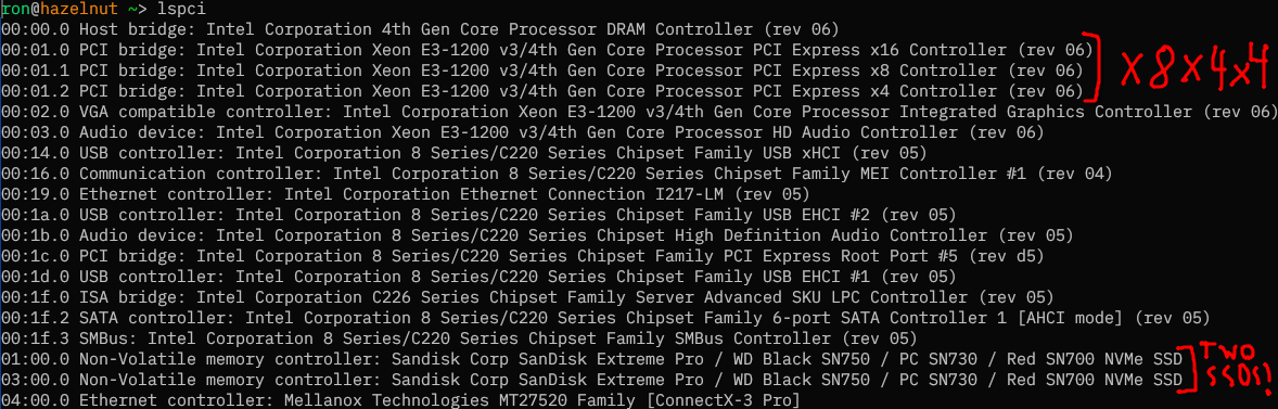
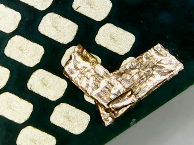
This is PCIe bifurcation (specifically, x8x4x4) being enabled on a Dell Precision T1700 SFF by connecting three pins on the bottom of the CPU using copper tape.
I wanted to have two NVMe SSDs and a 10G NIC in my new server, but the board (a Dell OptiPlex 9020 SFF) I was going to use for it only had two PCIe slots: PCIe 3.0 x16 from the motherboard, and PCIe 2.0 x4 from the PCH (Platform Controller Hub, Intel’s single-chip chipset family that they’ve used since 2009 replacing the separate northbridge and southbridge). This meant that I would either have to buy a PCIe switch (which are absurdly expensive, the cheapest 2-port PCIe 3.0 one I could find was £50 and most were a lot more), or find a way to enable PCIe bifurcation, which is supported by the CPU.
I found two articles by people who had done this before, on Haswell and Ivy Bridge, so I knew it was possible. For the PCIe lanes on the PCH this could be done in software (coreboot), but for the lanes on the CPU this needs to be done in hardware by physically setting the value of two pins on the CPU, CFG5 (U39), and CFG6 (U40) (unless the motherboard manufacturer connected those pins to the SuperIO or something, which Dell did not).
According to the CPU datasheet, both pins default to 0 if not terminated on the board, and:
| CFG5 | CFG6 | bifurcation |
|---|---|---|
| 0 | 0 | x8, x4, x4 |
| 0 | 1 | reserved |
| 1 | 0 | x8, x8 |
| 1 | 1 | x16 |
I found a schematic for my motherboard and they were connected only to pins on the XDP connector, which wasn’t soldered on (so there were just tiny pads). In order to set both pins to 0, I would need to somehow connect them to ground. I could either do it on the tiny XDP connector pads, or directly on the CPU. I found a map of the CPU pinout in the datasheet (which is quite confusingly vertically mirrored, and I couldn’t find a better one online), and decided it was easier to do it on the CPU, since there was a VSS/ground pin (V40) right next to CFG6, and it was near the edge of the CPU.
I got some copper tape and a cheap PCIe x16 to 4x M.2 adapter without a PCIe switch, and connected the three pins together (which was quite tricky to do, they’re tiny), and… it didn’t work. Only one PCIe controller showed up. I then recompiled coreboot with the other two controllers enabled in the devicetree, and it still didn’t show up.
It turns out that because Intel is evil, they had made the PCH artificially restrict which PCIe bifurcation modes the CPU was allowed to use. The OptiPlex 9020 SFF has a Q87 Express chipset, which is only allowed to use 1x16. I would need a Z87 or C220-series chipset to use the other modes. There’s no good reason for this restriction to exist, it’s purely artificial market segmentation, but I also don’t know of a way of bypassing it.
Fortunately, Dell also made the Precision T1700 SFF, which has an almost identical motherboard (to the point that the coreboot port works unmodified on both), except for one difference: it has a C226 chipset. The total cost of buying a Precision T1700 motherboard and the cheap PCIe-switch-less adapter was less than the cost of buying an adapter with a PCIe switch. Unfortunately, I only remembered about the Precision T1700 after I had already ordered an expensive adapter with a PCIe switch. Hopefully I’ll be able to return that when it arrives.
I swapped the motherboard, and… it worked! Except for one problem: the middle controller was not showing up for some reason. Only the first and fourth slots in my adapter worked. I suspect the connection between CFG5 and CFG6 wasn’t good enough, so only CFG6 ended up being set to 0. The datasheet doesn’t specify what happens in this case (“reserved”) but it seems to be that the first x8 and last x4 controllers are enabled, but not the middle x4 controller. When I redid it with another CPU (I was testing with a cheap CPU before doing it on my i7-4790k in case I ended up accidentally frying something) the problem went away and all 3 controllers showed up.
 0
0
 0
0
 2
2